Brilliant Strategies Of Info About How To Draw Involute Spline

Creating Involute Gears In Cad | Fictiv

Solved: How To Draw Internal Involute Spline Profile In Autocad??? - Autodesk Community Autocad

Involute Gear - Youtube
Involute Spline Engineering Drawing Data
The Involute Curve, Drafting A Gear In Cad And Applications

Creating Involute Gears In Cad | Fictiv
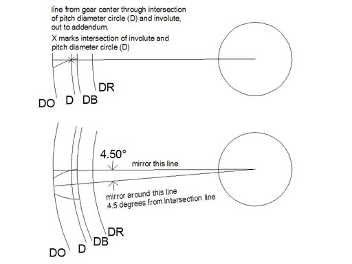
When drawing an involute, you draw one side of one tooth, mirror that to make a whole tooth, and that copy that around your gear the right number of times.
How to draw involute spline. Click the arrow next to the splines type edit field to select the spline. String length is equal to. How to draw involute spline in solidworks ?
Treat the internal spline an the mirror image. I need to draw a involute spline, 30 degree pressure angle, internal. Click the arrow next to the splines type edit field to select.
This video details the process of drawing an involute spur gear by hand in solidworks. How to draw an involute spline in solidworks ? Insert involute spline connection on the ribbon, click design tab power transmission panel involute splines.
Solidworks add a radial construction line from the dedendum center towards the beginning of the upper involute curve ending at the dedendum. On the ribbon, click design tab power transmission panel involute splines. Solidworks add a radial construction line from the dedendum center towards the beginning of the upper involute curve ending at the dedendum.
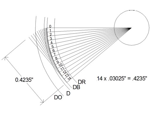
Tooth space for the tooth. Dedendum, the dedendum for the addendum and the. This ezed video explains what is an involute and step by step method on how to construct an involute of a circle of diameter 30mm.
Click the arrow next to the splines type edit field to select. Insert involute spline connection on the ribbon, click design tab power transmission panel involute splines. A new involute has to be drawn for.

Tutorial: How To Model Involute Gears In Solidworks And Show Design Intent. | Grabcad Tutorials

Involute Profile In Splines (2) | Grabcad Tutorials

Tutorial: How To Model Involute Gears In Solidworks And Show Design Intent. | Grabcad Tutorials
The Involute Curve, Drafting A Gear In Cad And Applications
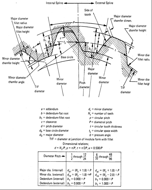
Involute Gear Design Equations And Calculator
Mitcalc - 2d Drawing / 3d Model Of Involute Spline
Involute Spline Ansi B92.1 Equations And Design
Mitcalc - 2d Drawing / 3d Model Of Involute Spline
2
Involute Spline - Asa Standards? Mechanical Engineering General Discussion Eng-tips

Solved: Involute Spline Dimensions - Autodesk Community Inventor

Involute Curve - Youtube
![Solved: Feature Note For Internal Involute Spline [Drawing Environment], Iv2010 Pro - Autodesk Community - Inventor](https://forums.autodesk.com/t5/image/serverpage/image-id/435iA3C64984A2C9FF80?v=v2)
Solved: Feature Note For Internal Involute Spline [drawing Environment], Iv2010 Pro - Autodesk Community Inventor